Return to the Robot

DSC_0016

The Anna Elise

It has been more than a month since my last blog post, and you’d be forgiven for thinking that I’d lost interest in robots. It *is* true that I have been rather distracted by customers, including a trip to the USA. It is also holiday season, and I have been to a music festival. However, except for last week when I was skipper and this week when I am chillng out on the Anna Elise, the robot has been in my suitcase on every trip, and I have actually been working hard on it. I just haven’t been able to get anything new to work until very recently.

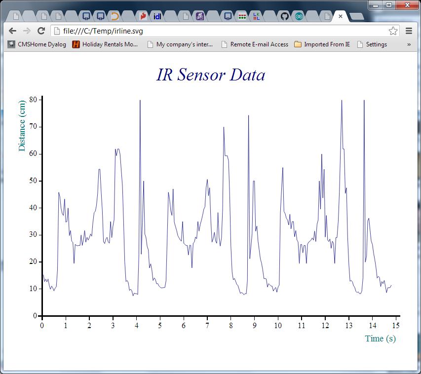
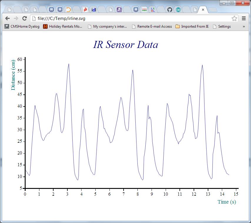
One problem was that robots do not travel particularly well. Put them in a suitcase every 3-4 days and bits quickly start falling off (if you have ever looked out the window of your plane and watched a baggage handling crew at work, that should be no surprise). I now have both 220v and 110v soldering irons (Thank You RadioShack!), and have so far been able to put humpty dumpty together again on arrival. But my last desperate attempt to collect some sonar data that I could publish before going sailing ended like this:

Rewriting the Raspberry Pi – Arduino Comms Program

The BIG reason for the lack of visible progress is that I decided that the time had come to rewrite the control program for the Arduino. The robot uses a Raspberry Pi running Dyalog APL as the main “brain”, but because a high-level language on a Pi isn’t a “real time” programming environment, we are using an Arduino to control the I/O pins. The idea is that, by implementing a very simple “front-end processor” on the Arduino, we will have a tool that APL can control at a high level, leaving timing-dependent work like controlling pulse-width-modulated output pins, which need to be continuously updated, to the Arduino.

The old control program had a number of limitations; most importantly, it was only really possible to monitor a single input pin. This was good enough until the sonar was added to the infra-red sensor. The program also contained hard-coded information about how pins were being used. Finally, it was quite simply a badly-written piece of Arduino C, subject to intermittent timing-related glitches because the original authors were unaware of certain limitations of the Arduino.

So I decided to write about 5 pages of new C code, and it took me a month and a bit to get back to blogging. Apart from the distraction of having to pretend to still be the CTO of Dyalog Ltd, the real problem is that I am not (usually) a C programmer. C is a rather unforgiving language. Or rather, it is a VERY forgiving language – it allows you to write code that will compile without warnings but just not work, because you unwittingly asked it to do odd things like truncate the content of a variable that you have used in a context which assumes a shorter type (etc, etc, and etc).

To stack the odds further against me, the default Arduino environment has no real debugger. In addition, the I2C bus that we are using to communicate between the Pi and the Arduino is very timing-dependent, which means that any attempt to step through the code will necessarily cause it to fail. Even the standard Arduino practice of monitoring diagnostic messages written to the serial interface cannot be used as it alters the timing enough to cause many I2C requests to fail. So after 2-3 weeks of wailing and gnashing teeth, I implemented my own simple logging mechanism to return diagnostic info via I2C and finally managed to move very slowly forward and complete the new control program. And I even RTFM and a few web pages written by people who had done this kind of thing before – in particular, this post by Wayne Truchsess was extremely helpful.

I was hoping to be able to publish some results of using the new Sonar, but I tried to do this on a jet-lagged Sunday morning sandwiched between returning from the USA and heading off to sail, and absolutely everything I did went wrong. The batteries died in the middle of my data collection and, to make the day perfect, when I found a new set of batteries, a wheel fell off (see the video above)…so I won’t be able to blog about the sonar data until I am back from the sailing trip at the end of July. However, I would like to talk a bit about the new control program.

I2CArduinoComm v0.2

As previously mentioned, we have a piece or Arduino C code (available on GitHub), which supports a simple command language which APL on the Raspberry Pi uses to issue instructions to set or read I/O pin values. The BIG difference compared to the old version is that ALL code that either reads or sets pin values has been moved to the loop() function, which (if my understanding is correct) is dispatched by the Arduino “operating system” when the O/S is not busy with other tasks. The old program would read and update pins immediately upon receipt of I2C messages. The I2C bus is quite critical with respect to timing, and the old code was spending too much time reading pin values when a data request arrived – so we were missing the timing window for getting a response back in time – and possibly interfering with other timing-dependent activities on the Arduino. The new program constantly maintains arrays containing the latest input values (done in the “loop” function), so all an I2C read request needs to do is to transmit the current values.

Command Language Extensions 

From a functional point of view, the main improvement is that the pin usage is completely configurable using a new “setup” command. At a lower level, the command language has been made more flexible. We no longer use a fixed command length; instead the first byte transmitted declares the length of the command (the first byte of all results is also the length of the response). The following commands are supported:

Command
Character
Command Name Description / Comments
I Identify Returns two bytes containing the major and minor version number of the ArdCom program (currently 0 2), followed by two bytes per defined pin (pin #, pin type).
R Reset Clears all pin definitions.
S Setup Declares pin types. Following the command character, triplets of (pin#, pin type, additional info) for each pin (see the pin type table below for details). “S” can be called several times in succession if the overall length of the command would otherwise exceed 32 bytes).
W Write Sets pin values: the command char is followed by pairs of (pin#, value).

Pin Setup

Each pin declaration included in a setup command consists of a triplet of bytes, containing the pin#, type character, and “additional info”. Only the “p” pin type currently makes use of the additional info – for other pin types this value is ignored.

Pin Type
Character
Type Name Description / Comments
A Analogue output Uses the analogWrite function to set the value.
D Digital output Uses digitalWrite.
S Servo output Uses Servo.write to update the pin value.
a Analogue input Uses analogRead.
d Digital input Uses digitalRead.
p Pulse input Uses pulseIn to read a pulse-width modulated input. If “additional info” is set, then this should be a digital pin number which is given a 10ms HIGH signal to tell the device to provide an input pulse.

See the Arduino Reference for descriptions of analogWrite, digitalWrite and the other functions mentioned above.

Reading Input Values

When an I2C read request is made (by APL on the Pi), the current values for all pins defined as inputs (in ascending order) are returned in a single transmission. The data stream contains two bytes (Most Significant Byte followed by LSB) for each input pin. If the control program wants to return diagnostic information, then the first data byte will have the value 254 and the rest of the transmission will be textual “log” data. 254 is an impossible value for the MSB of any input, because the maximum input value is 1023, which has an MSB value of 3. 254 was chosen rather than 255, which frequently occurs when there are transmission failures or other errors.

The ArdCom Class

A new APL class has been written to communicate with the new Arduino code. You can find the source code in the file ArdCom.dyalog in the GitHub repository. The DyaBot class has been updated to make use of the ArdCom encapsulation, the new version can be found in the Exampes folder in the repository. I will describe the in detail in my next blog post – probably not for another week, as the weather forecast looks superb for the next few days (probable route Faaborg-Aabenraa-Augustenborg-Gråsten-Flensburg-Sønderborg-Ærøskøbing).

Sonar Arrives for the Robot

Following the release of Dyalog APL for the Raspberry Pi came a hectic week with no time to play… But now the next sensor has arrived, so it is time to power the robot back up. In the video below, we practice turning it through 180 degrees using APL.

The big day will be the day after tomorrow, when the three mice (who were once blind) are bringing a bag of robot parts and coming to play with us. Jason and I will help them solder things together and get APL code up and running. We’ll work on getting our own sonar operational – and Jasons LCD display, if we can figure it out.

Dyalog APL now available for the Raspberry Pi!

Although the news had not yet appeared on the Dyalog webpage when this was written, the CTO blog has access to exclusive sources and is therefore able to present this scoop: The big day has finally come – Dyalog APL version 13.2 is now available to anyone with a Raspberry Pi, and can be downloaded immediately from http://packages.dyalog.com! We will of course be making official announcements via various channels over the next few days, so keep an eye on our web page – but remember that you saw it here first!

In the above clip, you can see that the Dyalog C3Pi got a little over-excited: while celebrating (and testing) the new release with an autonomous drive on my kitchen floor (in the middle of dinner preparations), the robot got a bit too close to an obstacle and dragged the on/off switch along a pillow, switching itself off in the process! A single infra-red sensor doesn’t give much information for autonomous driving, but we have placed orders for a high-definition sonar, which should arrive next week. Stay tuned for further developments!

A Full Implementation of Dyalog APL

Note that, although the Pi version of Dyalog APL is free for educational and non-commercial use, is not technically restricted in any way – it has exactly the same features as any other 32-bit Linux-based (Unicode) version of Dyalog APL.

You are also welcome to take a look at the User Guide before installing the software – it also contains useful links to other resources that you can use to learn about Dyalog APL. If you would like to take a look at APL but do not (yet) have Raspberry Pi, educational and non-commercial licenses are also available for Linux/x86 and Windows – and you can also try APL online at http://tryapl.org (apologies in advance if you have a tablet, good support for tablets is coming soon to TryAPL).

Visualising Sensor Data using APL on the Robot

As described in a recent post, our robot now has an Infra-Red distance sensor, which allows us to measure the distance from the front of the robot to the nearest obstacle. With respect to the autonomous navigation code that we wish to write, this will be the cornerstone! In order to evalute the perfomance of the sensor, we surrounded the robot with obstacles and commanded it to rotate slowly in an anti-clockwise direction, while IR data was collected 20 times per second:

RotatingC3Pi

Surrounded by obstacles, C3Pi rotates anti-clockwise and returns IR distance data every 0.05 seconds

Collecting the Data

We initialized the workspace by loading first the “RainPro” graphics package (which is included with Dyalog APL on the Pi), and then the robot code:

    )load rainpro                   Loads the graphics workspace
    ]load /home/pi/DyaBot           Loads the robot control code

The following function loops 300 times (once every 0.05 seconds), repeatedly collecting the value of the robot’s IRange property (which contains the current distance measured by the IR sensor). The call to the UpdateIRange method of the bot ensures that a fresh sample has just been taken (otherwise, the robot will update the value automatically every 100ms).

      ∇ r←CollectIRangeData bot;i;rc
 [1]    r←⍬
 [2]    :For i :In ⍳300
 [3]        :If 0=1⊃rc←bot.UpdateIRange
 [4]            r←r,bot.Irange
 [5]            ⎕DL 0.05 ⍝ Wait 1/20 sec
 [6]        :Else
 [7]            ∘∘∘ ⍝ Intentional error if update fails
 [8]        :EndIf
 [9]    :EndFor
      ∇

We can now perform the experiment as follows:

      iBot←⎕NEW DyaBot ⍬           ⍝ Instance of the robot class
      iBot.Speed←40 0              ⍝ 40% power on right wheel only 
      ⍴r←CollectIRangeData iBot    ⍝ Check shape of collected values 
300
      iBot.Speed←0                 ⍝ Let the robot rest its batteries
      1⍕10↑r                       ⍝ First 10 observations to 1 decimal 
15.3 12.8 13.7 12.7 13.7 11.4 9.9 11.1 10.4 9.4

Now that we have the data, the following function calls will create our first chart:

     ch.Set 'head' 'IR Sensor Data' ⍝ Set Chart Header
     ch.Set 'ycap' 'Distance (cm)'  ⍝     Y caption
     ch.Set 'xcap' 'Time (s)'       ⍝     X caption
     ch.Set 'xfactor'(÷0.05)        ⍝ Scale the x-axis to whole seconds
     ch.Plot data                   ⍝ Create the chart
     '/home/pi/irline.svg' svg.PS ch.Close ⍝ Render it to SVG

ir-sensor-data-raw

Removing the Noise with a Moving Average

The chart above suggests that the robot performed a complete rotation every 5 seconds or so with just under 100 observations per cycle. The signal seems quite noisy, so some very simple smoothing would probably make it easier to understand. The following APL function calculates a moving average for this purpose – it does this by creating moving sums with a window size given by the left argument, and dividing these sums by the window size:

       movavg←{(⍺ +/ ⍵) ÷ ⍺}  ⍝ Define the function 
       3 movavg 1 2 3 4 5     ⍝ Test it
 2 3 4

We can re-use the existing chart settings and plot smoothed data as follows:

      #.ch.Plot 7 movavg data      
      '/home/pi/irline.svg' svg.PS ch.Close

ir-sensor-data-smooth

Making Sense of It

The pattern is now nice and clear – but how does the map compare to the territory? We can use a “Polar” chart of the distance to see how the measured distances compare to reality:

     ∇ filename PolarDistance data;⎕PATH;mat;deg;window;smoothed;angles;movavg
[1]   ⍝ Polar IR Distance plot - "data" is one cycle of observations
[2]   ⍝ Note the -ve right margin to get the chart off-centre!
[3]
[4]    ⎕PATH←'#.ch'      ⍝ Using RainPro ch namespace
[5]    window←7          ⍝ Smoothing window size
[6]    deg←⎕UCS 176      ⍝ Degree symbol
[7]    movavg←{(⍺+/⍵)÷⍺} ⍝ Moving average with window size ⍺
[8]
[9]    angles←360×(⍳⍴data)÷⍴data ⍝ All the way round
[10]   smoothed←window movavg data,(¯1+window)↑data
[11]   data←(⌈window÷2)⌽data     ⍝ Rotate data so centre of window is aligned with moving average
[12]
[13]   Set'head' 'Infra-Red;Distance;Measurement'
[14]   Set('hstyle' 'left')('mleft' 12)('mright' ¯60)
[15]   Set'footer' 'Distance measured;every 0.05 seconds;while 3Pi was rotating'
[16]   Set'style' 'lines,curves,xyplot,time,grid,hollow'
[17]   Set'lines' 'solid'
[18]   Set'nib' 'medium,broad'
[19]   Set('yr' 0 60)('ytick' 10)
[20]   Set('xr' 0 360)('xtick' 15)('xpic'('000',deg))
[21]   Set('key' 'Measured' '7 MovAvg')('ks' 'middle,left,vert')
[22]
[23]   Polar angles,data,⍪smoothed
[24]   filename svg.PS Close  
     ∇

To align the chart with the picture, we need to:

  1. Extract the first 99 observations – corresponding to one rotation
  2. Reverse the order of the data, because the robot was rotating anti-clockwise
  3. Finally, rotate the data by 34 samples, to align the data with the photograph (the recording started with the robot in the position shown on the photograph)

We can do these three operations using the expression on the next line, and then pass this as an argument to the PolarDistance function, which creates another SVG file:

     onerotation←¯34⌽⌽99↑r
     '/home/pi/irpolar.svg' PolarDistance onerotation

ir-sensor-data-polar.jpgIf we compare the red line to the picture we started with, and take into account the fact that the robot was rotating quite fast and the IR sensor probably needs a little time to stabilise, it looks quite reasonable. The accuracy isn’t great, but with a little smoothing it does seem we should be able to stop little C3Pi from bumping into too many things!

Stay tuned for videos showing some autonomous driving, and the code to do it…


C3Pi Opens Eyes at the APL Moot

The "Three Blind Mice" at the APL Moot at the YHA in the Lee Valley

Sam Gutsell, Shaquil Sidiki and James Greeley (aka “Three Blind Mice”) at the APL Moot at the YHA in the Lee Valley

This weekend, the Dyalog C3Pi reached the final stop on the European spring tour, attending the British APL Association’s Annual General Meeting and “Moot” just north of London, where the robot met the famous mice from Optima. The day before, the C3Pi also travelled to an OSHUG meeting in London on Thursday, where Romilly Cocking was talking about quick2link. Alas, poor C3Pi was confined to a cardboard box due to problems with wiring up its new “eyes”:

Sharp "GP2Y0A21YK0F" IR sensors attached to the Dyalog C3Pi

Resistance is Futile!

Asimov’s third law of robotics states that a robot must protect its own existence. Thanks to the addition of a SHARP infrared distance measuring sensor, our robot is now capable of at least not running head first into walls or other obstructions (and if the obstruction is a spectator, we’re also providing some support for the first law)!

first-third-laws

C3Pi obeying the First and Third Laws of Robotics

Connecting the Sensor to the Raspberry Pi

The sensor is attached to an analog input pin on the Arduino (we picked pin #0). Our Arduino command interpreter, which allows APL on the Rasperry Pi to use the Arduino as a “controller” for analog and digital I/O, was extended with an “Analog Read” command consisting of the letter “a” followed by a byte giving the pin number and a dummy pad byte in order to ensure that the command length is 3 bytes (the fixed length simplifies the interpreter). Thus, if APL transmits (97 0 0) to address 4 on the I2C bus, and then issues an I2C read command, it will receive a string containing the current voltage (up to 5v, in 1024ths) measured – for example “a0:480;” if the input is 2v. We elected to include a confirmation of the pin number in the result, and separators which will allow us to send several sensor input values in a single string, as we add more sensors to the robot.

In the APLBot GitHub Repository, The DyaBot class has been extended to run a background thread which updates the value of a new property called “IRange”, every 100ms (a public method UpdateIRange can be called at any time to refresh the value). The input voltage is converted to a distance in centimetres, using the tables from the sensor datasheet. The next blog post will illustrate some of the data that we are now able to collect from the sensor.

The DrivePi game code also runs a background thread which monitors the value of IRange, and stops the wheels if the measured distance drops below 20cm – but this code still needs some testing and tweaking.

Accelerometer and Gyro on the Way

My experience to date is that controlling the robot is a little bit tricky, because the output of the wheels seems quite variable (changes from day to day, and from hour to hour). Determining the position of the robot using “dead reckoning” based on the voltage applied to the wheels seems unlikely to succeed. We either need to find some more reliable wheels – or find some sensors that can help us understand what is going on.

I have been able to lay my hands on an MPU-6050 motion tracking device from InvenSense. We’ll be trying to wire this up over the next couple of weeks and see whether it allows us to accurately track the motion of the robot. We will also soon take delivery of an ultra-sonic sonar mounted on a servo, so we can start measuring longer distances accurately (the IR sensor is really only suitable for collision avoidance). Once these are wired up, all we have to do is write “a little” APL code to do the localization and mapping!

Driving my Pi

Back from the APL meeting in Hamburg, where my C3Pi made it’s first appearance on German soil (and a few days meeting with APL users in Milan). I’ve extended the control program which was used to make last week’s figure 8 video to give me some “hand controls”. I do appreciate that it is inadvisable for humans to control motor vehicles directly, but in the privacy of my own home I have risked a little careful driving:

The APL Code

You can see the latest code at https://github.com/APLPi/APLBot. However, beware that significant changes will be made next week – both to the APL code and the Arduino / I2C interface layers. We will be adding support for our first sensor – an Infra-Red sensor that will allow us to measure the distance to the nearest obstacle (in front of the ‘bot) – and this requires some extensions.

The APL code currently consists of three files: I2C.dyalog, DyaBot.dyalog and DrivePi.dyalog. These need to be placed in the same folder on your C3Pi.

The I2C.dyalog file relies on the library lib2c-com.so, which will be installed along with Dyalog APL for the Pi when this becomes available.

The final piece of the puzzle is the control program for the Arduino. That’s in APLPi/I2CArduinoComm. Install it by following the relevant part of Jason’s instructions on building your own C3Pi.

The three APL code files implement the following layers:

I2C: A namespace which loads libi2-com.so and makes four interface functions available in the active workspace. Strictly speaking, this file belongs in the libi2c-com repo, and will move there when I have time to co-ordinate rewriting some test cases with Liam.

DyaBot: A class, built upon I2C, which allows APL applications to control the robot by setting a field named “Speed” to a 2-element vector containing values between ¯100 (full reverse) and 100 (full speed ahead) for each of the 2 wheels.

DrivePi: A namespace, built upon DyaBot, containing a function Run which provides a very simple “game interface” for driving the C3Pi, and a function Play which accepts 3-column matrices of (Right Wheel Speed, Left Wheel Speed, Duration) records, which are “played back”.

What next?

The ultimate goal of our project is to write some code which allows the C3Pi to perform Simultaneous Localization and Mapping (SLAM): The robot should be able to examine its surroundings, build a map, and accept high-level instructions to move from point to point, avoiding obstructions. As mentioned above, we’ll be addding the first collision-avoidance sensor next week. Once that is done, I’ll be back to discuss the other sensors that we are planning to add to the C3Pi in the coming weeks. I hope that some of you will join us in building your own robots and helping write the software!