Solving the 2014 APL Problem Solving Competition – Cryptography Problem 1

This post is a continuation of the series where we examine some of the problems selected for the 2014 APL Problem Solving Competition. I’ll start by looking at the cryptography problems from Phase II.

Cryptography Problem 1 – Vigenère Cipher

The cipher is described using a large table of letters, but you don’t need to create this table in APL. Instead, you can convert each letter of the key and the corresponding letter of the message to numbers; add them together; and then convert the result back to a letter. Some subtleties:

  • We want the result of the addition to “wrap around” at the end of the alphabet, so 25 + 1 = 26 (Z) but 25 + 2 = 27 which should wrap round to 1 (A). This is called modular arithmetic.
  • We can implement modular arithmetic easily using APL’s Residue primitive, but this works most naturally when the alphabet is numbered from 0 to 25, rather than from 1 to 26. To use 0-based numbering, I’ll set ⎕IO←0 in the code below.
  • An idiomatic way of converting letters to numbers is to look them up in the ⎕A, the upper case alphabet: ⎕A⍳⍵. To convert the other way we can simply index into ⎕A: ⎕A[⍵]. (For more comprehensive conversions between characters and numbers see the ⎕UCS system function.)

The code is then straightforward:

VigEncrypt←{
    ⎕IO←0                       ⍝ use 0-based numbering
    key←(⍴⍵)⍴⎕A⍳⍺               ⍝ convert key to numbers and expand to length of message
    ⎕A[26|(⎕A⍳⍵)+key]           ⍝ add key to message and convert back to characters
}

To encrypt the message we added the key (modulo 26). To decrypt, we need to subtract the key (modulo 26) instead, so we can go from VigEncrypt to VigDecrypt just by changing one character in the code. Note that the result of the subtraction might be negative, but Residue (unlike the remainder or modulo operations in some other programming languages you may have used) will still give us the correct result in the range 0 to 25. For example, 26|¯3 is 23.

VigDecrypt←{
    ⎕IO←0                       ⍝ use 0-based numbering
    key←(⍴⍵)⍴⎕A⍳⍺               ⍝ convert key to numbers and expand to length of message
    ⎕A[26|(⎕A⍳⍵)-key]           ⍝ subtract key from message and convert back to characters
}

Here are the functions in action:

      key←'KEIVERSON'
      key VigEncrypt'APLISFUNTOUSE'
KTTDWWMBGYYAZ
      key VigDecrypt key VigEncrypt'APLISFUNTOUSE'
APLISFUNTOUSE

To be continued…

The Diamond Kata

Acknowledgments

Morten Kromberg is the other co-author of this text but the blogging software prevents his being listed as such.

We are indebted to Jay Foad, Nick Nikolov, John Scholes, and Fiona Smith for comments on successive drafts of the MS.

The Problem

The diamond kata is a programming exercise used in the agile development, XP and TDD communities. [0, 1, 2, 3]. It first came to our attention in 2012 in discussions with Gianfranco Alongi of Ericcson AB, Sweden, and again more recently in [3]. The following problem description is from [2] (the description varies slightly in each of the above references).

We’re going to write a program that builds a diamond picture like this, for some set of letters from A to whatever:

--A--
-B-B-
C---C
-B-B-
--A--

Solutions in Dyalog APL

We are actually going to solve a slightly different problem: the function will have two arguments. The left argument is a scalar of the background element; the right argument is a vector of the “letters” to be used. The result described in the opening section can be produced as:

   '-' dia 'ABCD'
---A---
--B-B--
-C---C-
D-----D
-C---C-
--B-B--
---A---

(In an APL session, what you enter is indented and the resultant output is aligned at the left margin. As well, in this text, we sometimes present the indented-input/output pairs across the page.)

Making the argument the actual letters rather than the number of letters or the last letter, facilitates working with “alphabets” other than A-Z. For example:

   0 dia 3 1 4 2
0 0 0 3 0 0 0
0 0 1 0 1 0 0
0 4 0 0 0 4 0
2 0 0 0 0 0 2
0 4 0 0 0 4 0
0 0 1 0 1 0 0
0 0 0 3 0 0 0

The diamond result is readily seen to be composed of reflections of one of the quadrants. For example, '-' dia 'ABCD' (shown above) is composed of reflections of

A---
-B--
--C-
---D

The functions (reverse last axis) and (reverse first axis) provide the requisite reflections. If q is the quadrant shown above, then:

   ⌽q       q
---A     A---
--B-     -B--
-C--     --C-
D---     ---D

   ⌽⊖q      ⊖q
D---     ---D
-C--     --C-
--B-     -B--
---A     A---

There are various ways to stitch the quadrants together (and to drop the common middle row or column) to get the required result. The following is a terse way:

   f←{⍉⍵⍪1↓⊖⍵}

   f ⌽q          f f ⌽q        f⍣2 ⌽q
---D---       ---A---       ---A---
--C-C--       --B-B--       --B-B--
-B---B-       -C---C-       -C---C-
A-----A       D-----D       D-----D
              -C---C-       -C---C-
              --B-B--       --B-B--
              ---A---       ---A---

The same pattern (metakata?) of f⍣2 involving can be used to compute the minors of a matrix [4].

It remains to produce the quadrant q. We note that it is a diagonal matrix and resembles the identity matrix for which creation many techniques are known. We use two of the 34 different methods in [5].

The first method: For a vector with n letters, if each vector is followed by n copies of the background element, then the 2⍴n reshape of that rotates each row an additional step to the right, and the result is the required diagonal matrix.

   n←≢v←'ABCD'

   v,'-'⍴⍨s←2⍴n           s ⍴ v,'-'⍴⍨s←2⍴n
A----                  A---
B----                  -B--
C----                  --C-
D----                  ---D

The second method: for the proposed merge operator [6] ⍺ f merge ⍵ is an array like with at positions selected by f. As such, it is a functional version of selective assignment. Merge with 1 1∘⍉ as the operand does the trick.

   4 4⍴⍳16                1 1∘⍉ 4 4⍴⍳16
 1  2  3  4            1 6 11 16
 5  6  7  8
 9 10 11 12
13 14 15 16

   '-'⍴⍨2⍴n              'ABCD' (1 1∘⍉merge) '-'⍴⍨2⍴n
----                   A---
----                   -B--
----                   --C-
----                   ---D

Putting it together:

dia  ← {{⍉⍵⍪1↓⊖⍵}⍣2⌽s⍴⍵,⍺⍴⍨s←2⍴≢⍵}
diam ← {{⍉⍵⍪1↓⊖⍵}⍣2⌽⍵(1 1∘⍉merge)⍺⍴⍨2⍴≢⍵}


   '-' dia 'ABCD'         0 dia 3 1 4 2
---A---                0 0 0 3 0 0 0
--B-B--                0 0 1 0 1 0 0
-C---C-                0 4 0 0 0 4 0
D-----D                2 0 0 0 0 0 2
-C---C-                0 4 0 0 0 4 0
--B-B--                0 0 1 0 1 0 0
---A---                0 0 0 3 0 0 0

   '-' diam 'ABCD'        0 diam 3 1 4 2
---A---                0 0 0 3 0 0 0
--B-B--                0 0 1 0 1 0 0
-C---C-                0 4 0 0 0 4 0
D-----D                2 0 0 0 0 0 2
-C---C-                0 4 0 0 0 4 0
--B-B--                0 0 1 0 1 0 0
---A---                0 0 0 3 0 0 0

Further Examples

   ↑∘⎕a¨ 0 1 5 3           ⍝ four prefixes of the alphabet
┌┬─┬─────┬───┐
││A│ABCDE│ABC│
└┴─┴─────┴───┘
   '.' dia¨ ↑∘⎕a¨ 0 1 5 3  ⍝ apply dia to each prefix
┌┬─┬─────────┬─────┐
││A│....A....│..A..│
││ │...B.B...│.B.B.│
││ │..C...C..│C...C│
││ │.D.....D.│.B.B.│
││ │E.......E│..A..│
││ │.D.....D.│     │
││ │..C...C..│     │
││ │...B.B...│     │
││ │....A....│     │
└┴─┴─────────┴─────┘
   '.' {{⍉⍵⍪1↓⊖⍵}⍣2⌽s⍴⍵,⍺⍴⍨s←2⍴≢⍵}¨ ↑∘⎕a¨ 0 1 5 3
┌┬─┬─────────┬─────┐
││A│....A....│..A..│
││ │...B.B...│.B.B.│
││ │..C...C..│C...C│
││ │.D.....D.│.B.B.│
││ │E.......E│..A..│
││ │.D.....D.│     │
││ │..C...C..│     │
││ │...B.B...│     │
││ │....A....│     │
└┴─┴─────────┴─────┘

The last input expression is standalone (replacing dia in the penultimate input expression with its definition) and you can try it in a http://tryapl.org session.

Testing

Tests are often descriptive rather than prescriptive, asserting what a result should be rather than how to compute it. For that reason they tend to be more robust and easier to develop than the actual function. For example, it is much easier to test that r is a root of a polynomial than to compute it, or to check that S is a solution to an NP-complete problem than to derive it.

In this instance, we did not write the tests before writing the diamond functions, but we easily could have. The same expressive power in APL that enabled terse solutions of the diamond kata also enabled their concise and comprehensive testing.

testd d checks that d is a correct result of a diamond function, and returns a 1 if it is. Like the diamond functions, testd treats d in its totality, as an object (matrix) rather than as individual lines. This treatment allows straightforward statement of properties that would be more laborious otherwise. (For example, d≡⊖d and d≡⌽d assert that d is symmetric in the horizontal and vertical axes.)

assert←{⍺←'assertion failure' ⋄ 0∊⍵:⍺ ⎕signal 8 ⋄ shy←0}

testd←{                   ⍝ test the result of a diamond function
 assert (2=⍴⍴⍵)∧=/⍴⍵:     ⍝ square matrix
 assert (0=≢⍵)∨1=2|≢⍵:    ⍝ dimensions are 0 or odd
 assert ⍵≡⌽⍵:             ⍝ symmetric in vertical   axis
 assert ⍵≡⊖⍵:             ⍝ symmetric in horizontal axis
 n←⌈2÷⍨≢⍵                 ⍝ number of input "letters"
 q←(n,-n)↑⍵               ⍝ upper right quadrant
 assert (q=⍬⍴⍵)∨∘.=⍨⍳n:   ⍝ background or diagonal
 1                        ⍝ 1 iff everything OK
}

   testd '-' dia 'ABCD'
1

   testd 0 dia 3 1 4 2
1

If a check fails (or if there is an outright programming error), execution suspends at the first line with the error. While suspended an interactive debugging environment is provided for investigating the problem.

   testd 'ABCD'
assertion failure
testd[1] assert(2=⍴⍴⍵)∧=/⍴⍵: ⍝ square matrix
     ∧
   ⍵
ABCD
   ⍴⍵
4
   ⍴⍴⍵
1

testd is not a complete test, because it does not “know” what the specified background element or what the “letters” were. The operator T provides a complete test:

T←{                       ⍝ test a diamond function ⍺⍺
 d←⍺ ⍺⍺ ⍵                 ⍝ result of diamond function
 assert testd d:          ⍝ checks not knowing arguments
 n←≢⍵                     ⍝ number of input "letters"
 assert (⍴d)≡0 0⌈¯1+2×n:  ⍝ dimensions are 0 or ¯1+2×n
 assert (1≥n)∨⍺=⍬⍴d:      ⍝ background element
 assert ⍵≡1 1⍉(n,-n)↑d:   ⍝ "letters" in diagonal of quadrant
 1                        ⍝ 1 iff everything OK
}

⍺ dia T ⍵ checks that ⍺ dia ⍵ produces a correct result, and returns a 1 if it does (and suspends at the first line of error if it does not).

   '-' dia T 'ABCD'         '-' diam T 'ABCD'
1                        1

   0 dia T 3 1 4 2          0 diam T 3 1 4 1 5 9
1                        1

The following expression tests '-' dia x where x is a prefix of the alphabet ⎕a, from 0 to 26 letters:

   '-' (dia T)∘(⍴∘⎕a)¨ ¯1+3 9⍴⍳27
1 1 1 1 1 1 1 1 1
1 1 1 1 1 1 1 1 1
1 1 1 1 1 1 1 1 1

The following expression tests 0 dia n?n for n from 0 to 99. The “letters” are n?n, a random permutation of order n:

   0 (dia T)∘(?⍨)¨ 10 10⍴¯1+⍳100
1 1 1 1 1 1 1 1 1 1
1 1 1 1 1 1 1 1 1 1
1 1 1 1 1 1 1 1 1 1
1 1 1 1 1 1 1 1 1 1
1 1 1 1 1 1 1 1 1 1
1 1 1 1 1 1 1 1 1 1
1 1 1 1 1 1 1 1 1 1
1 1 1 1 1 1 1 1 1 1
1 1 1 1 1 1 1 1 1 1
1 1 1 1 1 1 1 1 1 1

References

  1. Rose, Seb, Recycling Tests in TDD, Claysnow Blog, 2014-11-23.
  2. Cockburn, Alistair, Thinking Before Programming, Alistair Cockburn Blog, 2014-11-29.
  3. Jeffries, Ron, TDD on the Diamond Problem, RonJeffries.com Blog, 2014-11-29.
  4. Rusk, John, An Experiment in Think-First Development, AgileWiki Blog, 2014-12-01.
  5. Hui, Roger, and Kenneth E. Iverson, J Introduction and Dictionary,1990-2014; \. entry
  6. Hui, Roger, Identity Matrix, Jwiki Essay, 2005-11-18.
  7. Scholes, John, Merge, Dfns, 2012-03-30.
  8. Legrand, Bernard, Mastering Dyalog APL, 2009-11.

NOTE: A full description and tutorial of the language can be found in [7].

Three-and-a-bit

The most obvious expression for computing π in APL is ○1. But what if you can’t remember how works, or your O key is broken, or you feel like taking the road less travelled? With thanks to Wikipedia’s excellent list of Approximations of π, here are some short sweet APL expressions for three-and-a-bit:

      3                                 ⍝ very short
3
      4                                 ⍝ not so sweet
4
      s←*∘0.5                           ⍝ let's allow ourselves some square roots
      +/s 2 3
3.14626436994197234232913506571557
      31*÷3
3.141380652391393004493075896462748
      +/1.8*1 0.5                       ⍝ Ramanujan
3.141640786499873817845504201238766
      s 7+s 6+s 5
3.141632544503617840472137945142766
      ÷/7 4*7 9
3.141567230224609375
      9⍟995
3.141573605337628094187009177086444
      355÷113
3.141592920353982300884955752212389
      s s 2143÷22                       ⍝ Ramanujan again
3.141592652582646125206037179644022
      +∘÷/3 7 15 1 292                  ⍝ continued fraction
3.14159265301190260407226149477373
      ÷/63 25×17 7+15×s 5
3.14159265380568820189839000630151
      (1E100÷11222.11122)*÷193
3.141592653643822210363178893440074
      (⍟744+640320*3)÷s 163             ⍝ Ramanujan yet again
3.141592653589793238462643383279727

This last one is accurate to more places than I ever learned in my youth!

Technical note: to get plenty of precision, these examples were evaluated with 128-bit decimal floating-point, by setting ⎕FR←1287 and ⎕PP←34.

For more on continued fractions, see cfract in the dfns workspace.

Solving the 2014 APL Problem Solving Competition – it’s as easy as 1 1 2 3…

Competition LogoThe winners of the 2014 APL Problem Solving Competition were recognized at the Dyalog ’14 user meeting and had a chance to share their competition experiences. Emil Bremer Orloff won the student competition and received $2500 USD and an expenses-paid trip to Dyalog ’14, while Iryna Pashenkovska took first place among the non-student entries and received a complimentary registration to Dyalog ’14. Our congratulations to them for their fine efforts! This post is the first of a series where we will examine some of the problems selected for this year’s competition. The problem we’ll discuss first is Problem 3 from Phase I dealing with the Fibonacci sequence.

Problem 3 – Tell a Fib Write a dfn that takes an integer right argument and returns that number of terms in the Fibonacci sequence. Test cases:

      {your_solution} 10
 1 1 2 3 5 8 13 21 34 55
      {your_solution} 1
 1
      {your_solution} 0   ⍝ should return an empty vector

Essentially, you start with the sequence 1 1 and concatenate the sum of the last 2 numbers to the end and repeat until the sequence has the correct number of terms. In Python, a solution might look something like this:

def fib(n): # return the first n elements of the Fibonacci sequence
    result = []
    a, b = 0, 1
    while 0 < n:
        result.append(b)
        a, b = b, a+b
        n -= 1
    return result

You can write nearly the same code in APL:

r←fibLooping n;a;b
  r←⍬
  (a b)←0 1
:While 0<n
  r,←b
  (a b)←b,a+b
  n-←1
:EndWhile

While it’s possible to write APL code that looks like Python (or many other languages), one of the judging criteria for the competition is the effective use of APL syntax – in this case, by avoiding the explicit loop. Two ways to do this are 1) using recursion and 2) using the power operator ().

Recursive Solution

      fibRecursive←{⍵<3:⍵⍴1 ⋄ {⍵,+/¯2↑⍵}∇⍵-1}

The neat thing about recursion is that the function keeps calling itself with a “simpler” argument until it reaches a base case and then passes the results back up the stack. Here the base case occurs when the argument () is less than 3 and the function returns ⍵⍴1 – it’s either an empty vector, 1, or 1 1 for values of of 0, 1 and 2 respectively. It’s easy to illustrate the recursive process by adding some code (⎕←) to display information at each level of recursion.

      fibRecursive←{⍵<3:⎕←⍵⍴1 ⋄ {⎕←⍵,+/¯2↑⍵}∇⎕←⍵-1}
      fibRecursive 10
9
8
7
6
5
4
3
2
1 1
1 1 2
1 1 2 3
1 1 2 3 5
1 1 2 3 5 8
1 1 2 3 5 8 13
1 1 2 3 5 8 13 21
1 1 2 3 5 8 13 21 34
1 1 2 3 5 8 13 21 34 55

The recursive solution above is termed “stack recursive” in that it creates a new level on the function call stack for each recursive call. We can modify the code slightly to implement a “tail recursive” solution which Dyalog can detect and optimize by avoiding creating those additional function call stack levels. You can see the effect of this as each level computes its result immediately:

      fibTail←{⍺←0 1 ⋄ ⍵=0:⎕←1↓¯1↓⍺ ⋄ (⎕←⍺,+/¯2↑⍺)∇ ⎕←⍵-1}
      fibTail 10
        fibTail 10
9
0 1 1
8
0 1 1 2
7
0 1 1 2 3
6
0 1 1 2 3 5
5
0 1 1 2 3 5 8
4
0 1 1 2 3 5 8 13
3
0 1 1 2 3 5 8 13 21
2
0 1 1 2 3 5 8 13 21 34
1
0 1 1 2 3 5 8 13 21 34 55
0
0 1 1 2 3 5 8 13 21 34 55 89
1 1 2 3 5 8 13 21 34 55

Power Operator Solution

      fibPower←{⍵⍴({⍵,+/¯2↑⍵}⍣(0⌈⍵-1))1}

The power operator is defined as {R}←{X}(f⍣g)Y. When the right operand g is a numeric integer scalar – in this case (0⌈⍵-1), the power operator applies its left operand function f{⍵,+/¯2↑⍵} cumulatively g times to its argument Y, which in this case is 1. Similar to the recursive solution, we can add ⎕← to see what happens at each application:

      fibPower←{⍵⍴({⎕←⍵,+/¯2↑⍵}⍣(0⌈⍵-1))1}
      fibPower 10
1 1
1 1 2
1 1 2 3
1 1 2 3 5
1 1 2 3 5 8
1 1 2 3 5 8 13
1 1 2 3 5 8 13 21
1 1 2 3 5 8 13 21 34
1 1 2 3 5 8 13 21 34 55
1 1 2 3 5 8 13 21 34 55

In discussing this blog post with my fellow Dyalogers, Roger Hui showed me a rather neat construct:

      fibRoger←{1∧+∘÷\⍵⍴1}     ⍝ Roger's original version
      fibBrian←{1∧÷(+∘÷)\⍵⍴1}  ⍝ tweaked to make result match contest examples
      fibRoger 10
1 2 3 5 8 13 21 34 55 89
      fibBrian 10
1 1 2 3 5 8 13 21 34 55

I’ve added the parentheses around +∘÷ to make it a bit clearer what the left operand to the scan operator \ is. Let’s break the code down…

      ⍵⍴1 ⍝ produces a vector of ⍵ 1's 
1 1 1 1 1 ⍝ for ⍵=5

Then we apply scan with the function +∘÷, which in this case has the effect of adding 1 to the reciprocal of the previous result:

      (+∘÷)\1 1 1 1 1
1 2 1.5 1.666666667 1.6

Note that the denominator of each term is the corresponding element of the Fibonacci series…

1 ÷ 1 = 1
2 ÷ 1 = 2
3 ÷ 2 = 1.5
5 ÷ 3 = 1.6666666667
8 ÷ 5 = 1.6

To extract them, take the reciprocal and then the LCM (lowest common multiple) with 1.

      1∧÷1 2 1.5 1.666666667 1.6
1 1 2 3 5

What happens if you want to accurately compute larger Fibonacci numbers? There’s a limit to the precision based on the internal number representations. Because fibRoger and fibBrian delve into floating point representation, they’re the most limited. (Roger points out that the J language has native support for extended precision and does not suffer from this limitation.)

Dyalog has a system variable, ⎕FR, that sets the how floating-point operations are performed using either IEEE 754 64-bit floating-point operations or IEEE 754-2008 128-bit decimal floating-point operation. For most applications, 64-bit operations are perfectly acceptable, but in applications that demand a very high degree of precision, 128-bit operations can be used, albeit at some performance degradation. Using 64-bit operations, fibBrian loses accuracy after the 35th term while using 128-bits extends the accuracy to 68 terms.

Even setting ⎕FR to use 128-bit operations and the print precision, ⎕PP, to its maximum, we can only compute up to the 164th element 34-digit 8404037832974134882743767626780173 before being forced into scientific notation.

Can we go further easily? Yes we can! Using Dyalog for Microsoft Windows’ .NET integration, we can seamlessly make use of the BigInteger class in the System.Numerics .NET namespace.
First we need to specify the namespace and where to look for it…

      ⎕USING←'System.Numerics,system.numerics.dll'

Then we make a trivial change to our code to use BigInteger instead of native data types…

      fibRecursive←{⍵<3:⍵⍴⎕NEW BigInteger 1 ⋄ {⍵,+/¯2↑⍵}∇ ⍵-1}

And we’re done!

So the next time someone walks up to you and asks “What can you tell me about the 1,000th element of the Fibonacci series?”, you can confidently reply that it has 209 digits and a value of
43466557686937456435688527675040625802564660517371780402481729
08953655541794905189040387984007925516929592259308032263477520
96896232398733224711616429964409065331879382989696499285160037
04476137795166849228875.

For other APL Fibonacci implementations, check out this page.

Why Dyalog ’14 was a Shear Delight

rot55

Recent versions of Microsoft Windows support touch screens, which of course means that applications can respond to events originating from touches. Microsoft calls these events “gestures”.

Dyalog decided to add support for gestures to version 14.1 and so projects were planned, designs were designed, code was coded and, at Dyalog ’14 (#Dyalog14), a demonstration was demonstrated. The video of that demonstration is here

The three most interesting gestures are “pan”, “zoom” and “rotate”; I needed a good demo for the rotate gesture. I had an idea but was unsure how to implement it, so I decided to ask the team. Here’s the email I sent (any typos were included in the original email!):

“Does any have code (or an algorithm, but code ‘d be better) to rotate a matrix by an arbitrary angle. The resulting matrix may then be larger than the original but will be filled with an appropriate value.
Does the question makes sense? For the conference I want to demonstrate 14.1 support for Windows touch gestures, one of which is a “rotate” gesture, and I thought that a good demo would be to rotate a CD cover image when the gesture is detected. So I need to be able to rotate the RGB values that make up the image.”

There were a number of helpful responses, mainly about using rotation matrices, but what intrigued me was Jay Foad’s almost throw away comment: “It’s also possible to do a rotation with repeated shears”

That looked interesting, so I had a bit of a Google and found an article on rotation by shearing written by Tobin Fricke. The gist of this article is that shearing a matrix three times (first horizontally, then vertically and then again horizontally) effects a rotation. An interesting aspect of this (as compared to the rotation method) is that no information is lost. Every single pixel is moved and there is no loss of quality of the image.

I’m no mathematician, but I could read my way though enough of that to realise that it would be trivial in APL. The only “real” code needed is to figure how much to shear each line in the matrix.

Converting Fricke’s α=-tan(Θ/2) and ϐ=sin(Θ), we get (using for Θ):

a←-3○⍺÷2
b←1○⍺

and so, for a given matrix, the amounts to shift are given by:

⌊⍺×(⍳≢⍵)-0.5×≢⍵

where is either a or b, depending on which shift we are doing.

Wrapping this in an operator (where ⍺⍺ is either or ):

shear←{
(⌊⍺×(⍳≢⍵)-0.5×≢⍵)⍺⍺ ⍵
}

Our three shears of matrix , of size s, can therefore be written as:

a⌽shear b⊖shear a⌽shear(3×s)↑(-2×s)↑⍵

Note the resize and pad of the matrix before we start so that we don’t replicate the edges of the bitmap. The padding elements are zeros and display as black pixels. They have been removed from the images below for clarity.

The final rotate function is:

rotate←{
shear←{(⌊⍺×(⍳≢⍵)-0.5×≢⍵)⍺⍺ ⍵}
a←-3○⍺÷2 ⋄ b←1○⍺ ⋄ s←⍴⍵
a⌽shear b⊖shear a⌽shear(3×s)↑(-2×s)↑⍵
}

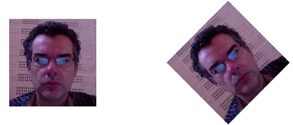
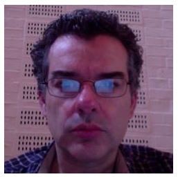
Let’s look at a 45° rotate of a bitmap called “jd”.

jd.CBits←(○.25)rotate jd.CBits

Prior to performing any shears our image is:

rot0

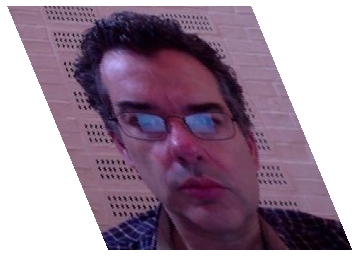
After the first shear it becomes:

rot1

After the second shear it is:

rot2

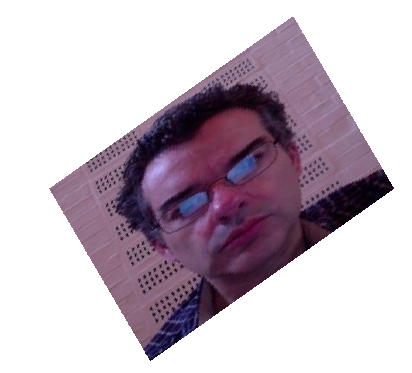
And after the third shear it is:

rot3

All nicely rotated.

Turning to a Heading with an MPU-9150

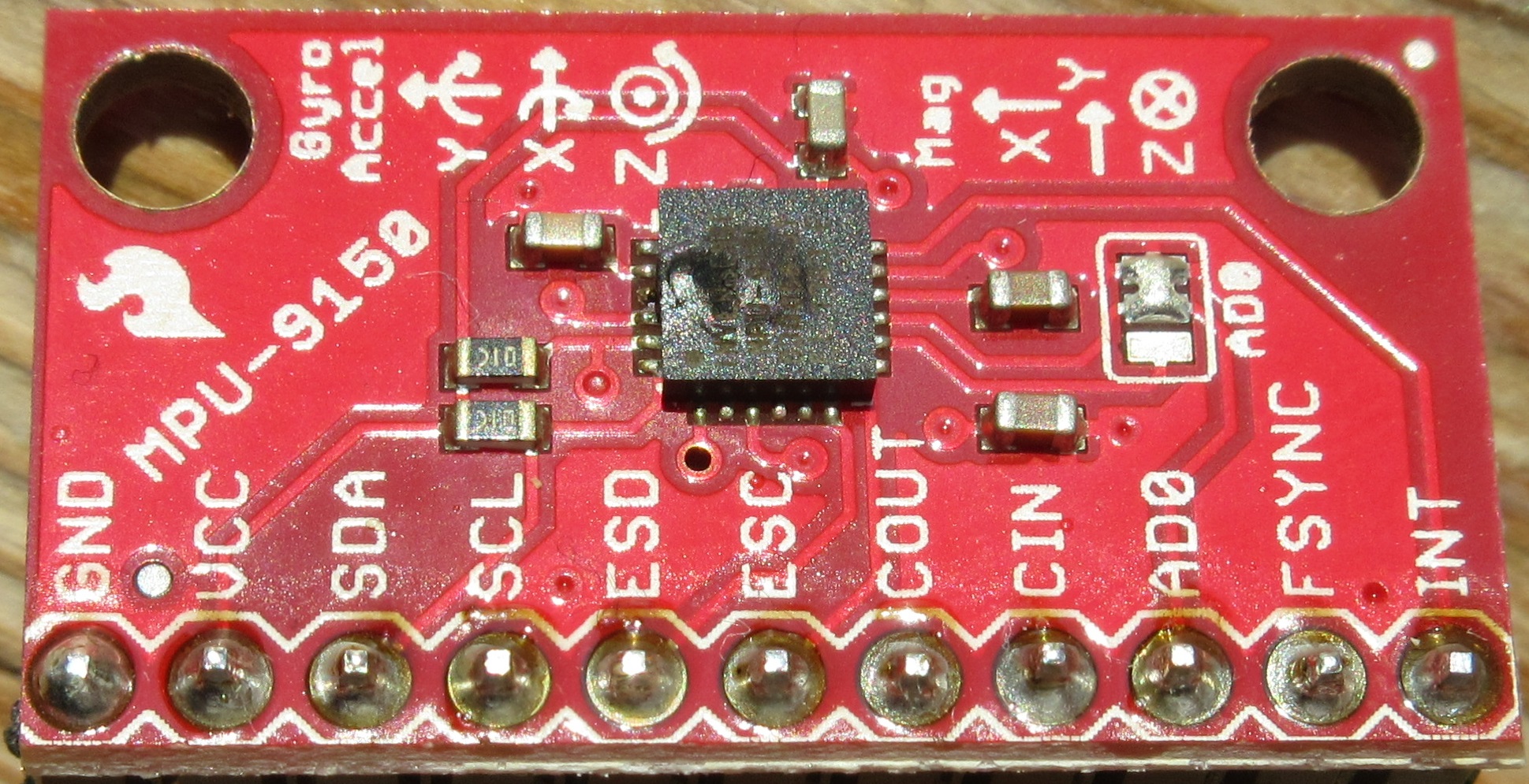
As the odour of fried electronics dissipates in the air, I’m unexpectedly afforded the opportunity to write this blog post a day or two earlier than planned. The on-board compass was exhibiting significant deviation, so I consulted my nephew Thorbjørn Christensen at DTU-Space. Thorbjørn makes a living designing magnetometers for space agencies around the world, and he suggested I use a ribbon cable to move the IMU away from the bot as a first step towards understanding the issue. He did warn me to be very careful when attaching it. I still don’t understand what I did wrong, but the evidence that I screwed up is pretty definitive: there are burn marks around every single connector and the IMU chip looks a bit soft in the middle. Most importantly, it no longer reports for duty on the Raspberry Pi’s I2C bus!

A fried IMU-9150

A fried IMU-9150 (click to enlarge)

The good news (apart from the fact that the Raspberry Pi, the Arduino and all other ‘bot components seem to have survived) is perhaps that, since I cannot play with the compass until I have a replacement, I found the time to write about where I am at the moment…and take some time out to work on my presentations for Dyalog ’14 (for those who managed to register before the user meeting in Eastbourne sold out, I still hope to do a ‘bot presentation on the evening of Tuesday September 23rd).

Introducing the MPU-9150

For the last few weeks, I have been using my “bot time” to play with the MPU-9150 breakout board that is attached to our ‘bot. The MPU-9150 is more or less identical to the 6050 that we were using earlier this summer to make gyro-controlled turns but also includes a magnetic compass, which will allow us to know the direction that we are heading in – making it a 9 degree of freedom inertial measurement unit, or “9-dof IMU” (9 = 3 gyro axes + 3 accelerometer axes + 3 compass axes).

RTIMULib

I was extremely happy to discover that Richard Barnett had shared his RTIMULib on GitHub. RTIMULib is a Linux library that produces “Kalman-filtered quaternion or Euler angle pose data” based on data from a 9-dof IMU. Jay Foad at Dyalog was quickly able to provide me with a couple of additional C functions designed to be easy to call from Dyalog APL. Jay’s fork of RTIMULib is also available on GitHub. Since we can assume that we are driving on a flat surface, I have just been using two items from the wealth of information provided by this library: the current rate of rotation and the current compass direction – in both cases around the vertical (or “z”) axis.

My First Compass-Controlled Rotation

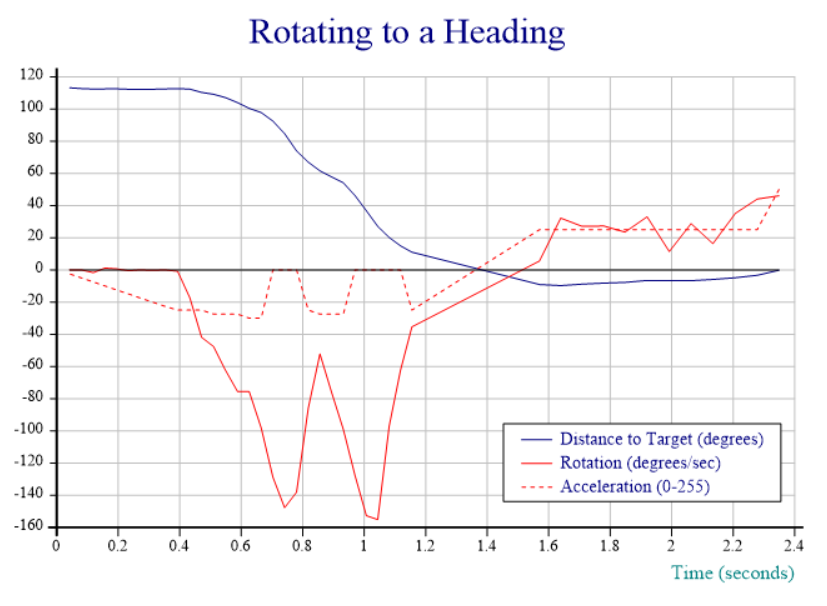
Due to the fried IMU, I am unable to post a video recording; fortunately, at the moment where I toasted the chip, the Dyalog session output still contained output data from the last run of the function I am working on, which aims to provide smooth rotation to a selected compass heading. In the chart below, the red line tracks the speed of rotation and shows that the “smooth” part still needs work – the speed oscillates quite violently between 60 and 150 degrees per second. The blue line shows the number of degrees that the ‘bot still needs to turn to reach the desired heading. The dotted red line is slightly mislabeled: rather than acceleration, it actually shows the power applied to the motors via a digital-to-analog converter that accepts values between 0 and 255, producing between 0 and 5v of voltage for the DC motors:

Rotating to a compass heading

Commentary:

  • From 0 to 0.4 seconds, we slowly increase power until we detect that rotation has started. We note the power setting required to start rotation.
  • 0.4 to 0.7 (ish), we detect acceleration and hold the throttle steady (increasing it very slightly a couple of times when acceleration appears to stop).
  • 0.7 to 1.1 seconds, cruise mode: whenever speed is above the target of 100 degrees/sec, we idle. When speed is below 100, we re-apply power at a level that was sufficient to start the rotation.
  • 1.1 to 1.4 seconds: We are less than 30 degrees from target, and the target velocity and thus power is reduced proportional to the remaining distance (at 15 degrees, we are down to 50 deg/sec)
  • 1.4 to 1.6 seconds: We detect that we rotated too far, and slam on the brakes, coming to a stop about 10 degrees from target.
  • 1.6 to 2.3 seconds: since we are less than 10 degrees from target, we enter “step” mode, giving very brief bursts of power at “start rotation” level, idling, and watching the heading until we reach the goal.
  • 2.4 seconds: We count the bursts and, after 10, we double the power setting to avoid getting bogged down (you cannot see the bursts in the chart, it only records the power level used for each one). A little more patience would have been good, this probably means we overshot by a bit.

The “Heading” Function

Achieving anything resembling smooth movement is still some way away, mostly due to the fact that motor response to a given input voltage varies enormously from motor to motor and between different applications to the same motor. The strategy described above is implemented by a function named “Heading”, which can be found in the file mpu9150.dyalog in the APLBot folder on GitHub. An obvious improvement would be to have the robot self-calibrate itself somehow and add a model of how fast rotation speeds up and slows down (based on, and constantly adjusted with, observed data), in order to dampen the oscillations. I intend to return to this when I have a new IMU (and my other user meeting presentations are under control).

This has turned out to be a lot harder than I imagined: suggestions are very welcome – please leave comments if you have a good idea!